


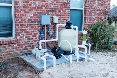
In the January issue of AQUA, the Pool & Hot Tub Alliance (PHTA) Service Council shared five steps for proper pool pump selection. Now that you have taken those steps and selected the right pump for your project, the PHTA Service Council explains how to install the pump to best meet energy efficiency and safety standards.
First, we need to make sure that we have plenty of room between the last 90-degree elbow and the inlet to the pump. This will ensure that the vaporized water (air) has time to recombine back into the stream of water before reaching the impeller. Water vaporizes in the elbow and returns to a fluid as the pipe straightens. This is not the same as cavitation! If the air makes it to the impeller, it will implode due to the low-pressure area, which can destroy the pump over time. Imbalanced flow can also cause stress on impellers, bearings, and seals.
Leave four to five times the pipe diameter in straight pipe before pump strainer housing, filters, and flow switches. ANSI/PHTA/ICC-15 2021 American National Standard for Residential Swimming Pool and Spa Energy Efficiency recommends four times the pipe diameter of straight pipe in front of the pump, but several manufacturers have their own requirements of up to eight times the pipe diameter! As always, it is important to read the manufacturer's installation guide.
In our January article, we selected the Pentair IntelliFlo3 VSF 3.0HP as the pump for our example project. We will continue to use that as our example pump. Its installation guide states:
- Suction line diameter should be the same or larger than the return line diameter.
- Do not install 90-degree elbows directly into the pump inlet or outlet.
- Valves, elbows, or tees installed in the suction line should be no less than five times the suction pipe diameter from the pump inlet.
- Return line should have 6 inches of straight pipe before elbows, tees, or valves.
- Note: Read the installation and maintenance guide before installation of the new variable-speed pump for location, plumbing and fittings, valves, and electrical installation.
Now that we have installed the IntelliFlo3 3.0HP, the next step is to verify the total dynamic head (TDH) of the system with the newly installed pump. When completed, the calculated maximum flow rate shall be verified by using a vacuum gauge and a pressure gauge to determine the TDH loss. That value is applied to the installed manufacturer's pump curve to validate the maximum flow rate value, or by using a flow meter accurate to ± 5%.
Install a vacuum gauge into the drain plug on the pump strainer housing. This is the vacuum side of the system. Then, install a pressure gauge on the volute housing of the pump. This is the pressure side of the system.
ANSI/PHTA/ICC-7 2020 American National Standard for Suction Entrapment Avoidance in Swimming Pools, Wading Pools, Spas, Hot Tubs and Catch Basins Section 4.4.5.1 describes the "maximum system flow rate — unsecured control systems residential and public pools method" for measuring and computing flow rate and TDH. Review this section for more details.
Each design of the filtration pump is tested to generate a performance curve that indicates the flow rate that the pump will produce when pumping against resistance (head). Even though the pump is capable of a wide flow range, the TDH of the circulation system determines what the flow rate of the pump will be. The TDH of the system at the desired flow rate must be carefully calculated so that the pump will produce the desired flow rate.
Below is a chart with many calculations for points on the TDH curve for this particular system taken from actual gauge readings. In truth, only two points are needed. One at maximum speed and one nearer to half speed.
Three points are needed to plot a curve but one of those points is always 0 gpm at 0 feet TDH. The chart that follows is a good exercise and shows the pump from 10 to 100% in intervals of 5%. It also shows the correlation between % speed to actual gpm of the system, but the curve can be plotted from just two required points and 0,0.
An IntelliFlo3 VSF 3.0HP that is on a particular pool system running at 3,050 RPM could see a savings of 48.7% in power by reducing the speed by 20%. At 3,050 RPM or 87% speed, the IntelliFlo3 VSF 3.0HP consumes approximately 1,570 watts.
The 20% reduction in speed results in a reduction in power consumption from 1,570 watts to 805 watts, representing a 48.7% reduction in power consumption from the pumps. This reduction in pump speed equates to a reduction in flow from approximately 81 gpm to 65 gpm. If the pump was on an eight-hour schedule, it was moving approximately 39,000 gallons of water per day. With the reduced pump speed, a 10-hour run schedule would be needed to move the same amount of water for filtration every day. This change goes from 12.5kWh per day to 8kWh per day, which represents a 36% reduction in energy consumption per day, without sacrificing any water filtration loss.

Looking back at "Step Five: Select a Pump" in the January article, we talked about how each manufacturer creates a certified pump curve for each model it sells. Pump curves show the relationship between the head on the vertical axis and flow rate on the horizontal axis for that model of pump and will always start high on the left and drop to the right. Note the efficiency curves.
When we were selecting a pump, we replaced the actual calculated TDH of the system from the pump with the calculated turnover period to a maximum of six hours plotted on the IntelliFlo3 3.0HP performance curves to determine our ideal plot point. With installation of the IntelliFlo3 3.0HP and having taken the TDH of the system with the new pump installed by using the ANSI/PHTA/ICC-7 Section 4.4.5.1 "maximum system flow rate — unsecured control systems residential and public pools method," we now have the actual system head curve plotted from 10 to 100% in intervals of 5%.
For the pump we are installing, it is not appropriate to flow more than 82 gpm through a 2-inch pipe size. Looking at the installation, the 100% or 3,450 RPM is 80 gpm. That meets the International Swimming Pool and Spa Code (ISPSC) specifications for safety on velocity. With a 20% reduction in speed, the installation is running at 63 gpm, which is 6FPS on the velocity on a 2-inch pipe size. That meets the requirements in ANSI/APSP/ICC-15 for energy efficiency. With a 50% reduction in speed or 1,750 RPM on the installation, the pump is running at 37 gpm. 36 gpm is the minimum flow rate to be considered. With Title 20, the low-speed rotation rate cannot be more than half of the maximum rotation rate.
For public pools, the aquatic venue shall run a six-hour turnover rate when open to bathers. On a 27,275-gallon public pool, 75 gpm is needed. That would be running at 95% speed on the pump while the aquatic venue is open to bathers. According to ANSI/PHTA/ ICC-2 2023 American National Standard for Public Pool and Spa Operations and Maintenance, the circulation rate shall be permitted to be reduced during periods that the aquatic venue is closed for use, provided that acceptable water quality — including but not limited to clarity and chemical levels in accordance with ANSI/APSP/ICC-11 2019 American National Standard for Water Quality in Public Pools and Spas — are met prior to reopening the aquatic venue for public use. So if we reduced the pump speed to 80% speed, that is 63 gpm while the pool is closed. It is recommended to bring the pump speed back to a six-hour turnover rate of 75 gpm at 95% speed two hours before the pool opens to the public.
For a residential swimming pool at 27,275 gallons, provisions in the federal energy code prohibit turnover rates faster than six hours for residential pools. That is 75 gpm at 95% speed of the pump. The ISPSC Section 810.1 on turnover residential swimming pool circulation systems states that a turnover rate of at least once every 12 hours is essential to maintaining water clarity and quality. On this pool, that would be 37 gpm at 50% speed on the pump. We will run our high speed at 63 gpm and 80% speed on the pump to run all cleaners, spas, and the heater. Our low speed on the pump can be run at 46 gpm and 60% speed on the pump with a 10-hour run time.
You can take this method of pump sizing and use it on any manufacturer's certified pump curve. The real intent of the federal energy code is to slow pumps down. We do not usually need 3,450 RPM to keep residential pools clean, but that is what we have sold for years. Now we need to sell the public on energy savings using variable-speed pumps operating at much less RPM.
To properly size and set up a variable- speed pool pump, start by creating a chart that shows the system's TDH in relation to the gpm flow using a flow meter. This step ensures that your system is operating efficiently, helping to avoid unnecessary energy consumption. Once you have that data, compare it to a velocity-to-feet-per-second chart, factoring in your pipe size to determine optimal flow rates.
Taking the time to carefully analyze these variables will not only extend the life of your equipment but also lead to long-term energy savings and better pool performance. Accurate sizing is key to achieving both cost-efficiency and system reliability.
For more details, charts, and example calculations, please read the full article from the PHTA Service Council on phta.org.
This article first appeared in the March 2025 issue of AQUA Magazine — the top resource for retailers, builders and service pros in the pool and spa industry. Subscriptions to the print magazine are free to all industry professionals. Click here to subscribe.